Architectural Analyses
CodeScene’s architectural analyses calculates Hotspots, Change Coupling, Code Health, and more at the system level of your high level design; all the analysis information that is available on a file level in CodeScene is available on an architectural level too.
The architectual analyses are enabled by configuring your architectural definitions. Note that the definition phase can be largely automated via the CodeScene UI.
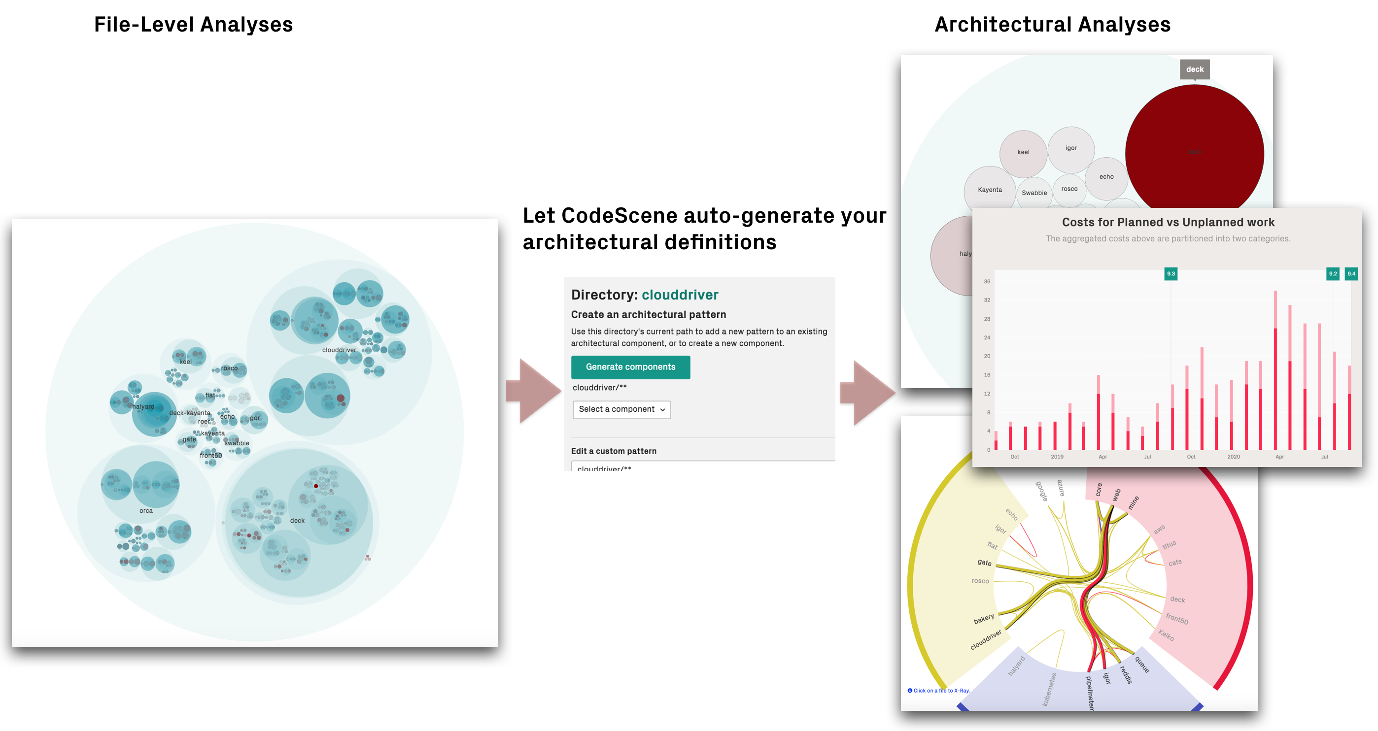
Fig. 116 Let CodeScene auto-generate your architectural definitions so that you can analyse hotspots, coupling, and knowledge distribution on a system level.
What is an Architectural Component?
An Architectural Component is a logical building block in your system. For example, if you build a Microservices architecture, each microservice could be considered a logical block. Similarly, if you organize your code in layers (MVC-, MVP-, MVVM-patterns, etc.), each layer would be a logical block.
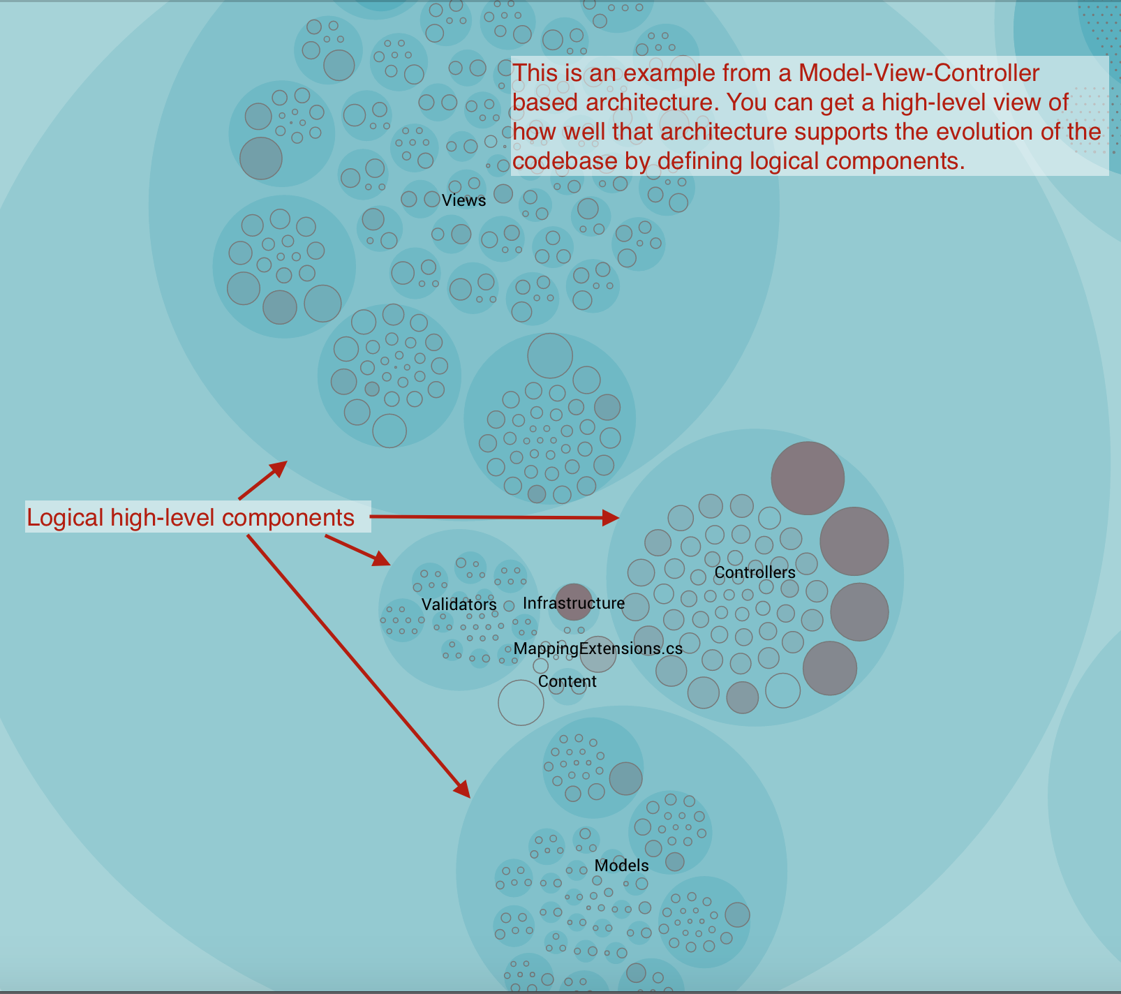
Fig. 117 An example of architectural components.
An Architectural Component could also be much more coarse. For example, let’s say that you’re interested in the co-evolution of your application code versus the test code. Perhaps because you suspect that you spend way too much effort on keeping your automated tests up to date. In that case, you’d define two Architectural Components: Application Code and Automated Tests.
You’ll learn to define your components in the next section. Before we go there, let’s have a look at the end result.
As you see in Fig. 118, CodeScene presents a hotspot analysis on architectural level. This gives you a high-level view of how your development activity is focused. You also see that you get the social knowledge metrics on an architectural level too. We’ll discuss that in more detail later in this guide to learn how we use them to analyse complex architectures like Microservices.
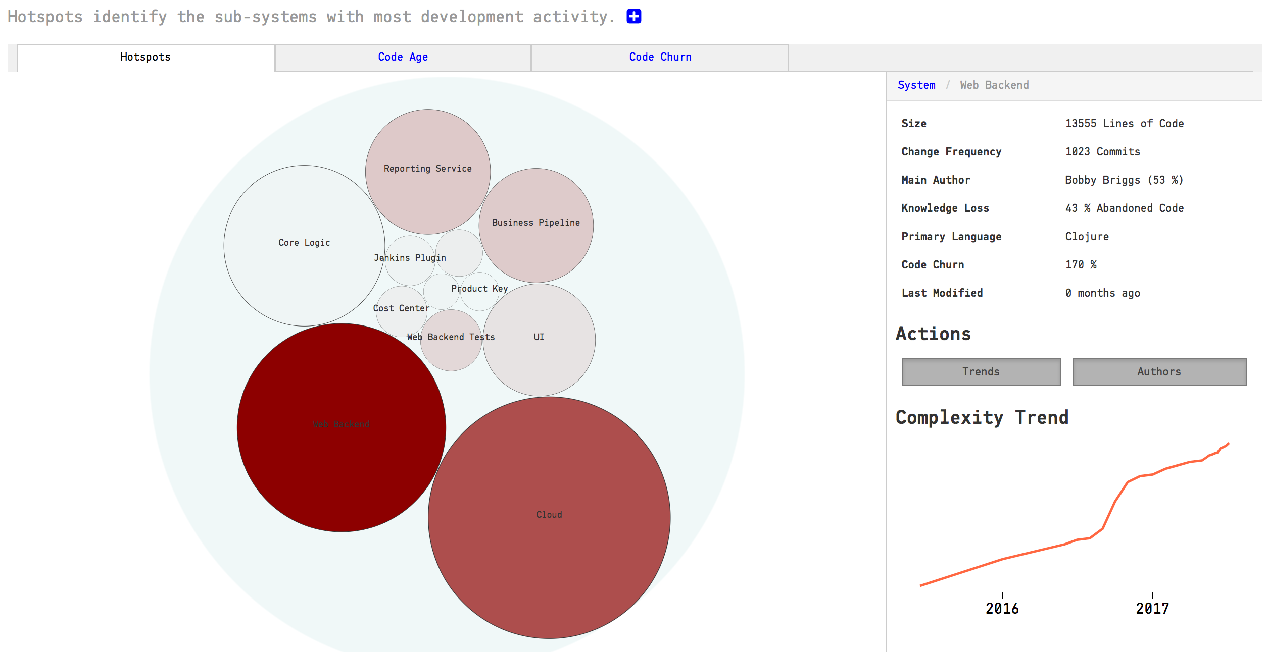
Fig. 118 High level architectural hotspots analysis.
Define your Architectural Components
CodeScene offers flexibility in how you define your components. The tool uses glob patterns to identify the files that belong to a specific component as illustrated in Fig. 119.
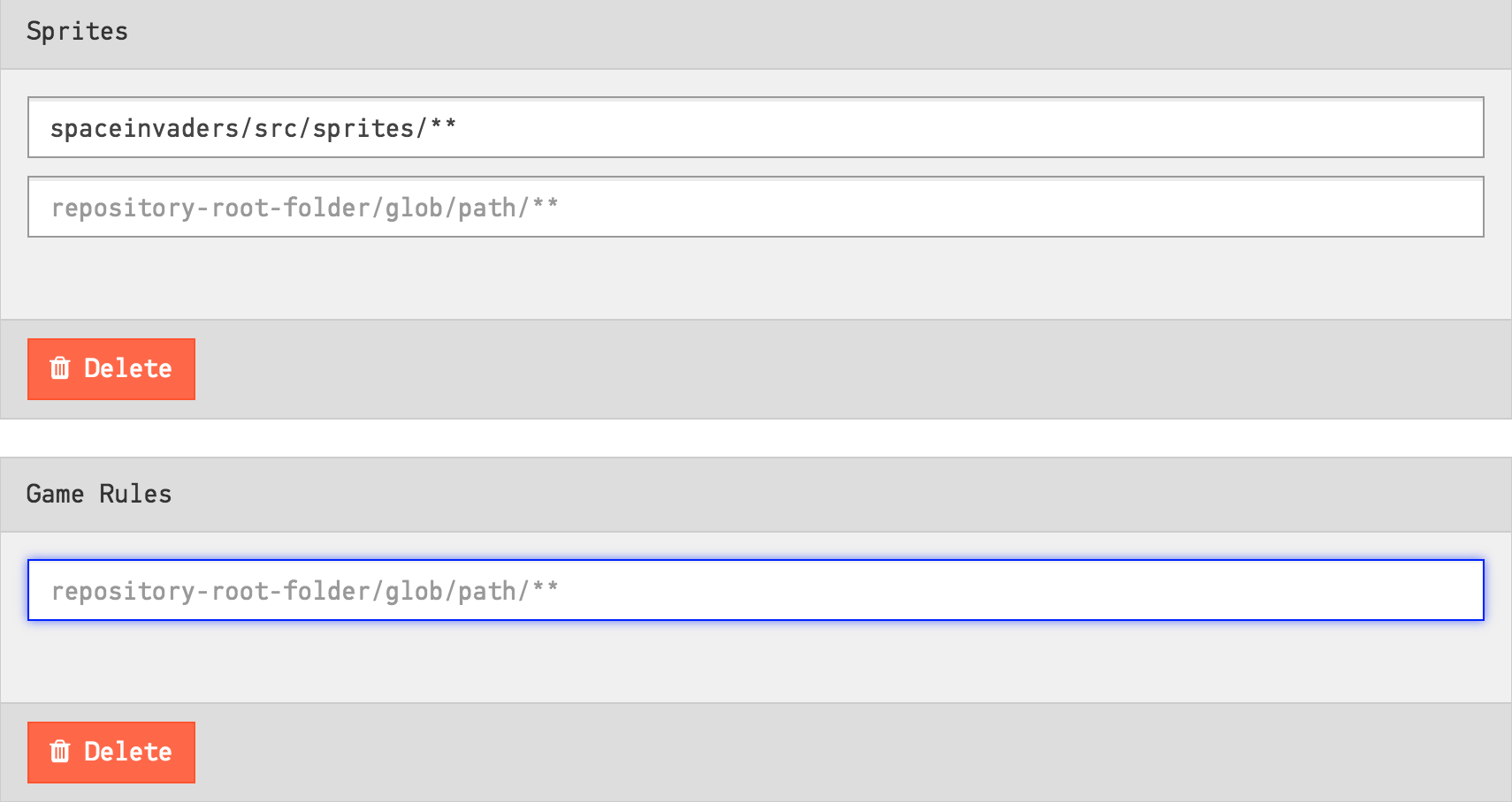
Fig. 119 Configure architectural components by specifying glob patterns for each logical component.
As you see in the picture above, you need to specify a pattern and the name of your component. All content in your codebase that matches your glob pattern will be assigned to an architectural component with the name you specified.
Let’s consider the example above to learn more about the format. The configuration in Fig. 119 specifies the pattern spaceinvaders/source/sprites/**. That means that all content under the folder spaceinvaders/source/sprites will be considered as the architectural/logical component Sprites.
You can also map multiple folders to the same architectural component. A common example on this is when you want to consider the application code and its associated unit tests as one logical unit. In this case you’d add a second pattern to the Sprites component in Fig. 119: spaceinvaders/test/sprites/**.
Use the Architectural Component Editor
The most common way of defining your architectural components is to use the Architectural Component Editor. In the “Architecture” tab of your project’s configuration pages, a large button leads to the Editor.
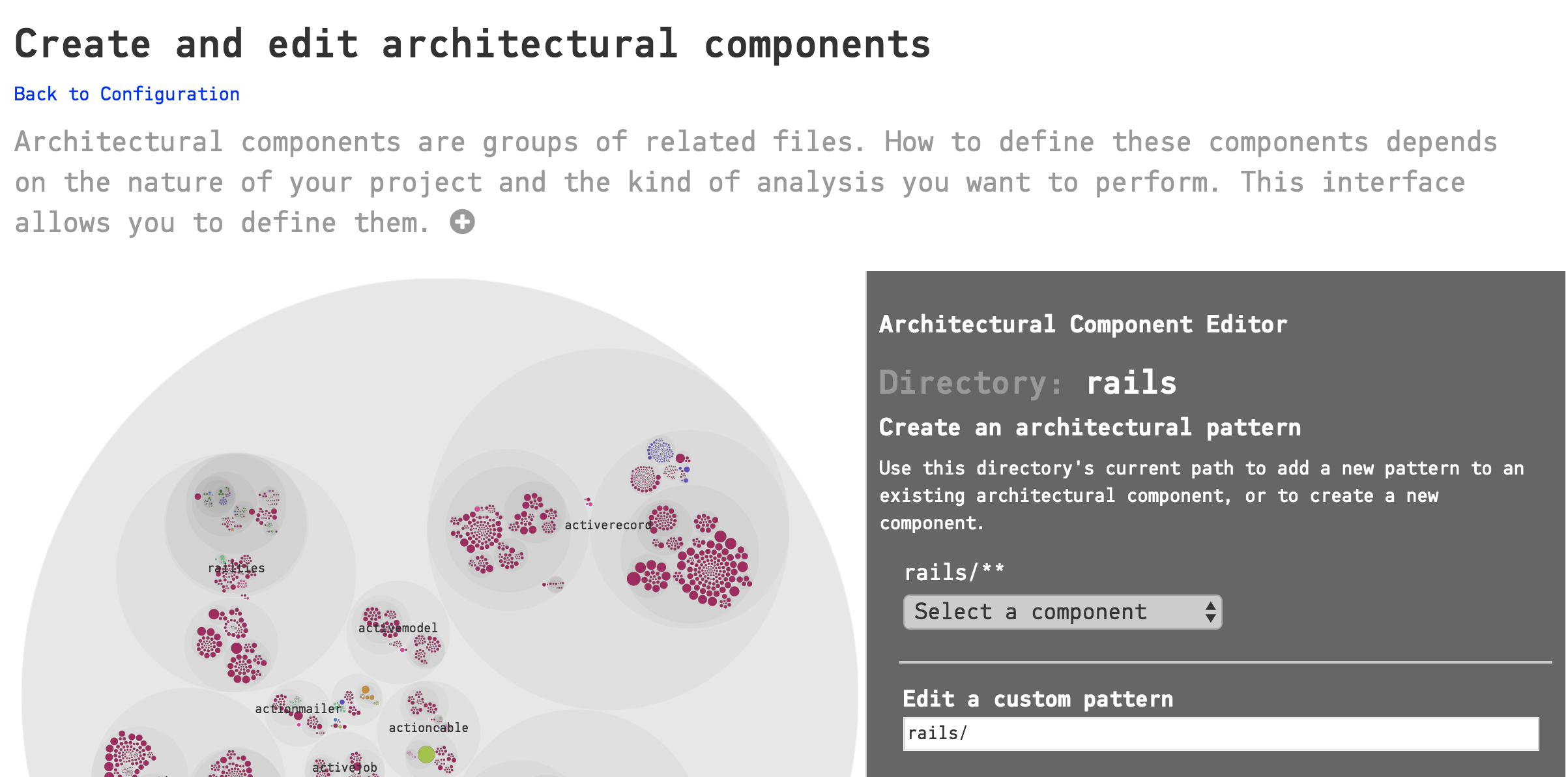
Fig. 120 CodeScene’s Architectural Component Editor provides a visual interface to your project’s files.
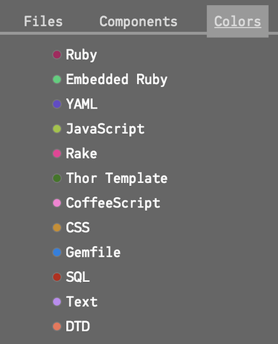
The Editor provides a visual interface to the files in your project. For this reason, it can only be used after you run an initial analysis. Once CodeScene is aware of the files in your project, it will provide you with the same circular visualization used for Hotspots and other analyses. You can zoom in and out to choose the parts of your project that you want to include in a Component. The colors of the circles indicate the type of files. A legend is available in one of the tabs of the sidebar:
Auto-Generate Architectural Components
In most codebases, the directory structure maps to the component view. If that’s the case, then you can let CodeScene auto-generate a mapping for you:
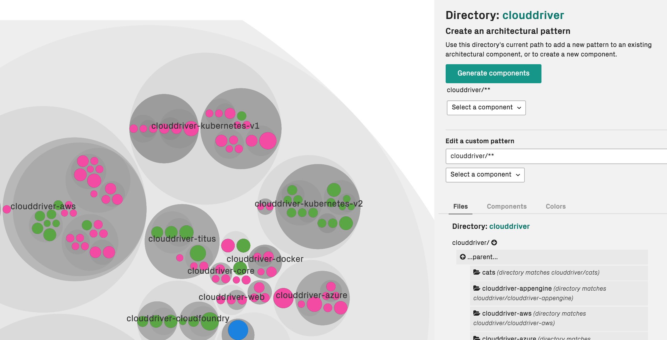
Fig. 121 Let CodeScene auto-generate your architectural definitions from the directory structure.
Navigate to a folder containing the directory structure of interest and press Generate components. CodeScene will prompt you for a prefix. This prefix is optional, and typically used to indicate a hierarchy.
Map Architectural Components manually
Optionally, you can also provide the architectural defintions manually.
When you have located a directory or a file that you wish to include in a Component, you have two choices at the top of the sidebar on the right:
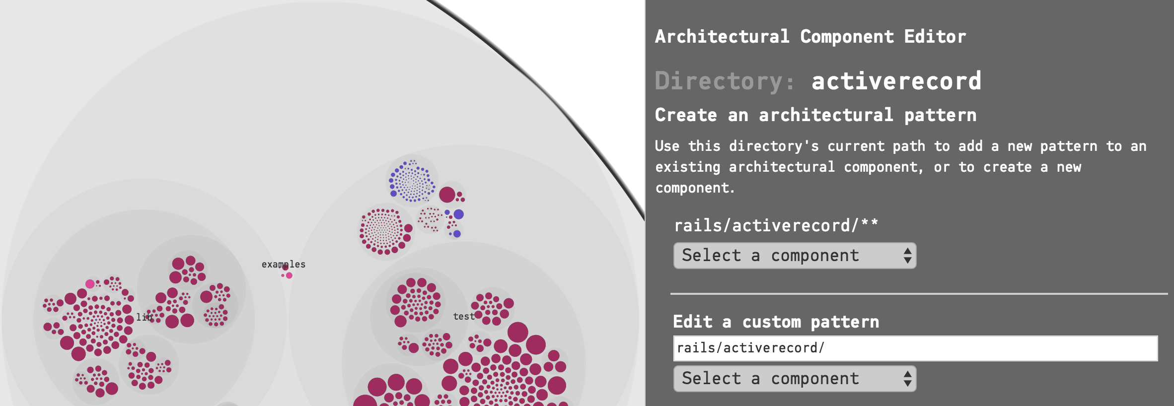
Fig. 122 Choose either the pattern for the current directory, or write your own pattern.
The most common action here is to click on “Select a component” under the first pattern, which, in the example above is rails/activerecord/**. This pattern will match all the files and subdirectories in the activerecord directory. You can either add the pattern to an existing Component, or create a new Component based on your selection.
The other choice is to write a custom pattern. In this example, if we were only interested in the .yml files in the activerecord directory, we could create a pattern like this:
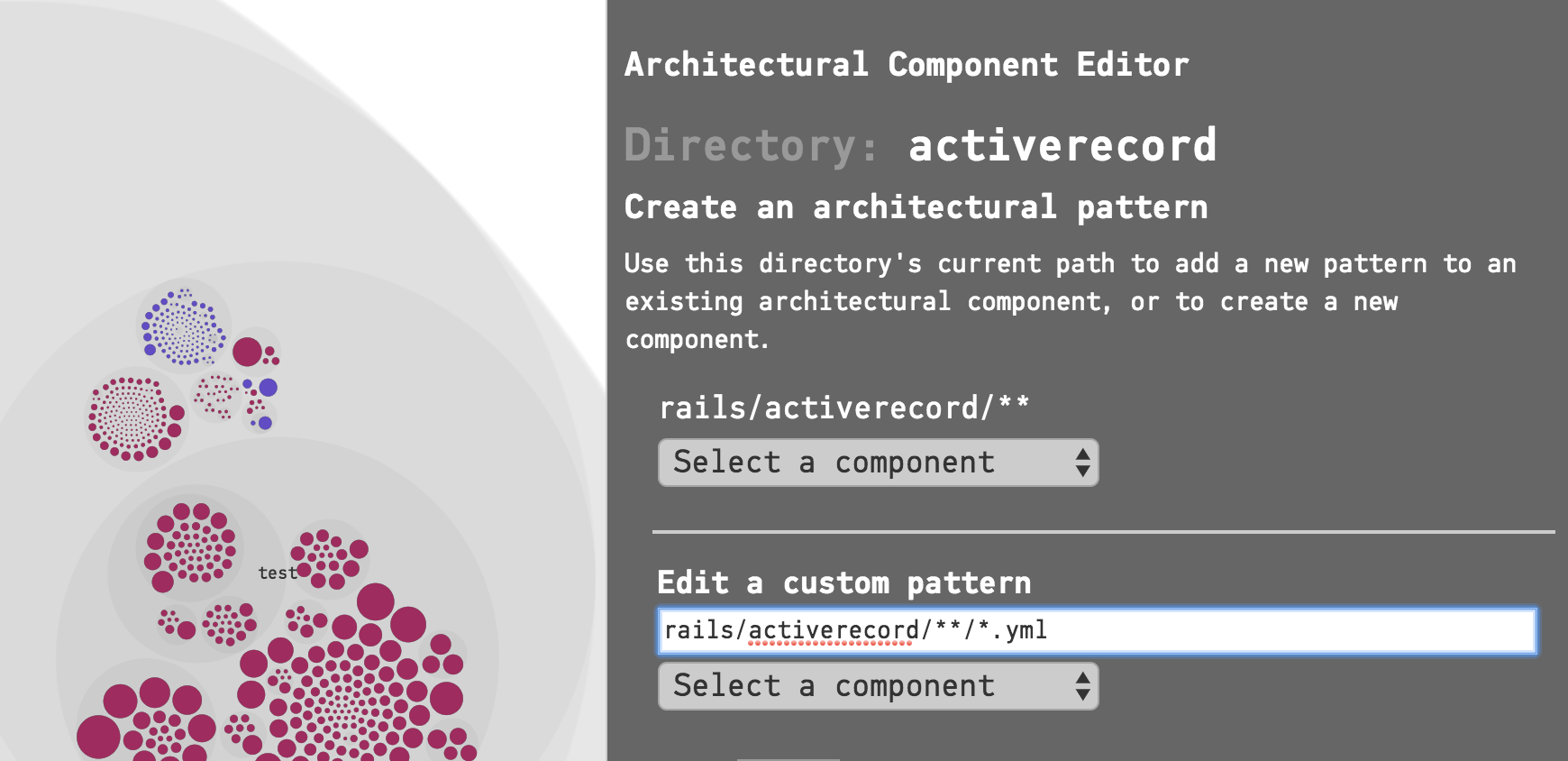
Fig. 123 A custom pattern that selects all the .yml files inside a directory.
This way, while using the visual interface, you still have the full power of glob patterns. Note that patterns are validated and must begin with the project root of the corresponding Git repository (rails/ in this example). or with *. The interface will prevent you from entering invalid patterns.
If you make a mistake, you can remove the pattern from the Component:
Fig. 124 Remove a pattern
The Architectural Component Editor also comprises a form-based view which you will find by scrolling further down the page.
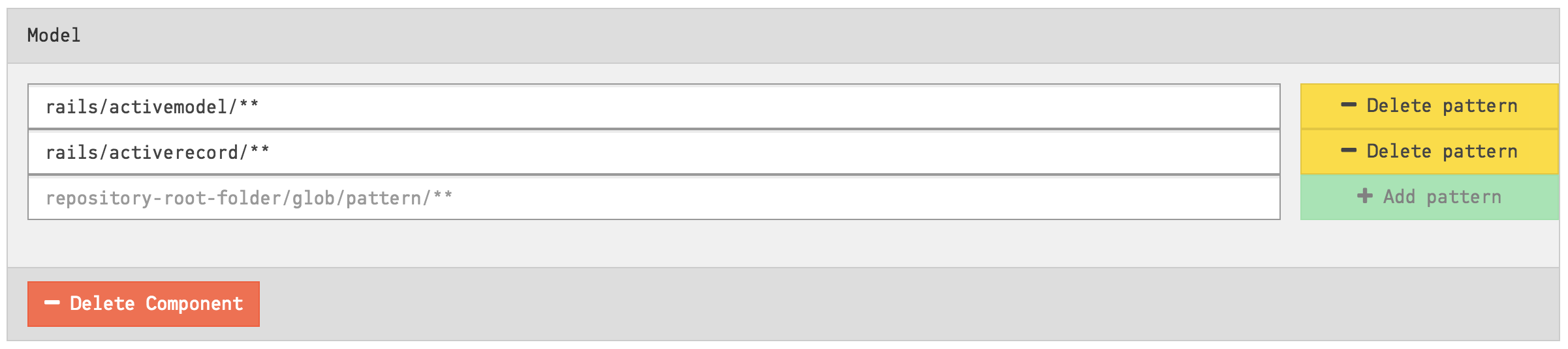
Fig. 125 The Editor also has a form-based view
You can make changes here just like in the visual interface, adding, editing or deleting components and patterns. Note that when a component contains zero patterns, it is deleted.
Changes are only stored when you click on the “Submit” button at the bottom of the page. Your new Architectural Components will be used the next time an analysis is run on your project.
Import or Export Architectural Component Definitions
Instead of specifying the patterns manually in the section above, you can import a CSV file with the definitions. This is a simpler option in a large system where you can script the generation of the CSV to import:
Your CSV file must not include a header row.
The CSV file shall contain two columns: 1. the Component Name and 2. its Glob Pattern.
The fields in your CSV are separated by commas.
Fig. 126 provides an example on a CSV file used to import architectural components.
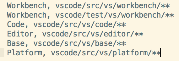
Fig. 126 Import your definitions of architectural component from a CSV file with this format.
The file content above defines five architectural components and maps each one of the to a logical architectural name. As you see, you can map several folders to the same architectural component. The Workbench component above is an example on this. As we import the file, CodeScene will generate a definition for Workbench as illustrated in Fig. 127.
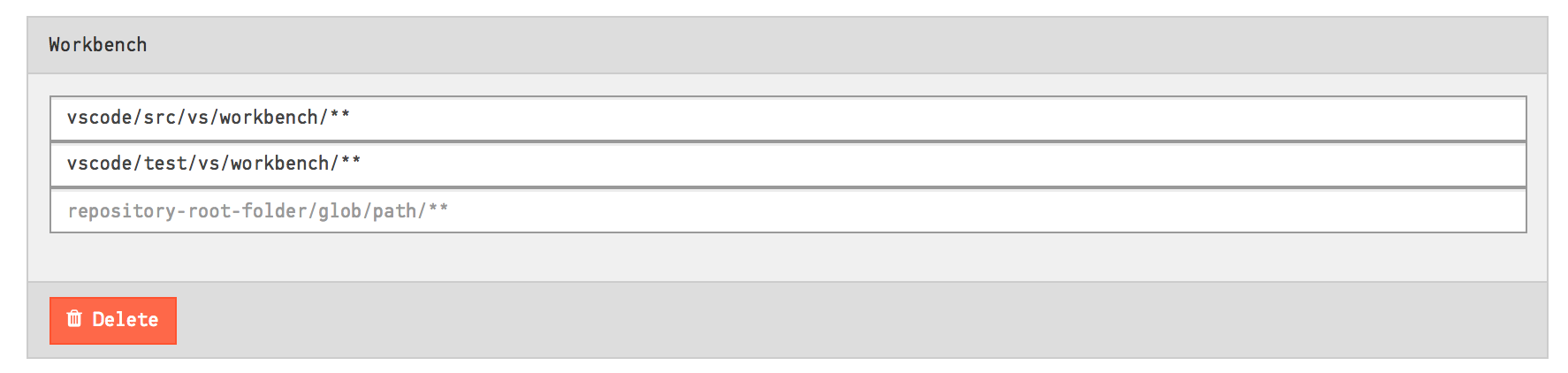
Fig. 127 Map two separate folders to the same architectural component.
You can also share architectural components between projects by exporting them to a CSV file and then importing them in another project.
System Complexity Trend
CodeScene calculates a trend of how your system, as a whole, has evolved over time.
Please note that you need to enable this analysis; It’s expensive in terms of analysis time, which is why it’s optional. Fig. 128 shows how to enable the trends.
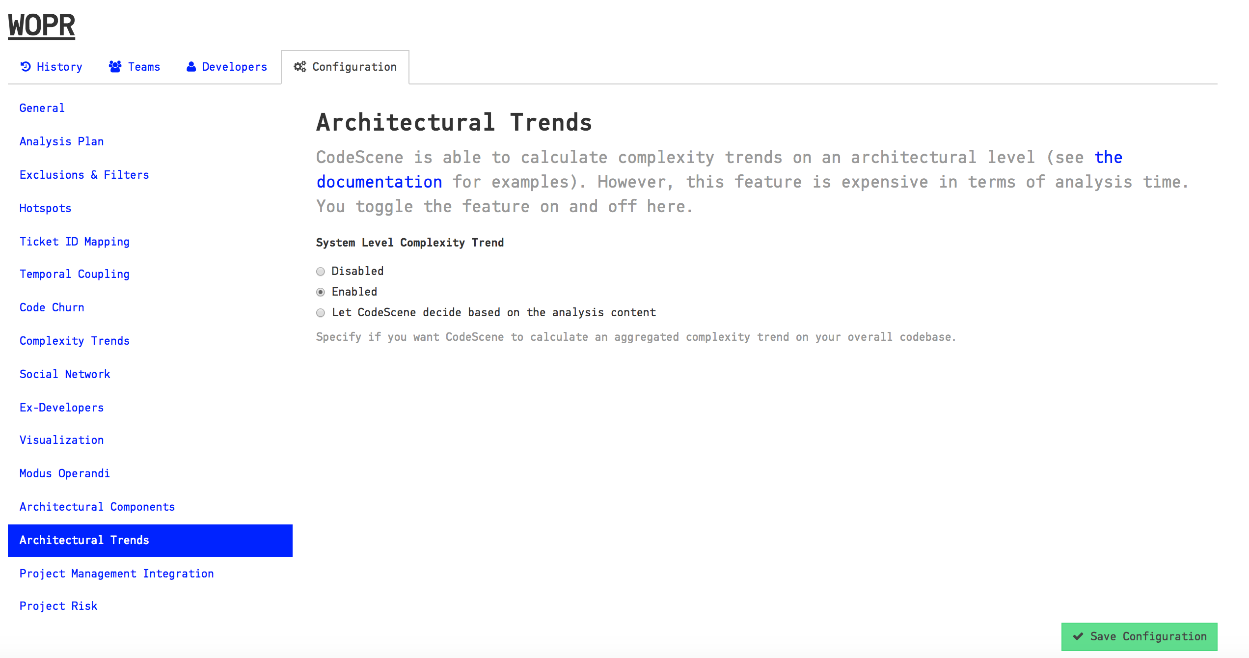
Fig. 128 Enable the trend analysis of architectural components in your project configuration.
Once you’ve enabled the architectural trends, CodeScene will calculate an overall view of the evolution of your system as illustrated in Fig. 129.
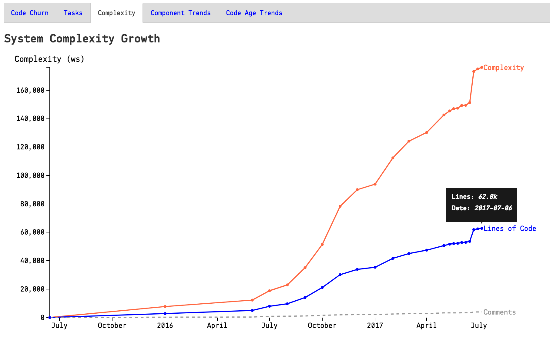
Fig. 129 The evolution of the complete codebase.
You use this information to see if the system has stabilized and entered a maintenance phase or if it still evolves rapidly. You can also correlate the growth patterns to how the staffing has looked over time - did more people really resulted in a faster growth?
CodeScene also presents a breakdown of the system complexity per architectural component as illustrated in Fig. 130.
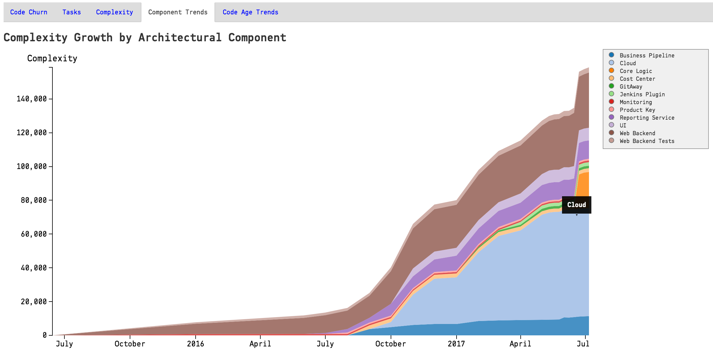
Fig. 130 The architectural trends let you view how the development effort has shifted over the years.
Know the Biases in System Complexity Trends
The system/architectural complexity trends don’t take all your historic development into consideration. The trends are based upon the active amount of code. That is, only the code that’s included in your repositories today will be considered. More specific, this means that:
If you have deleted whole files and folders in your codebase it won’t reflect in the trends.
We also want you to be careful when interpreting the results of an analysis that use a shorter time span than that of the whole repository lifetime. In such a shorter analysis period, only the files with active development activity are included in the codebase. You’ll still be able to see a trend and reason about possible complexity growth in your code. However, the absolute numbers are likely to be lower than the total amount of code; Only files that you have modified are included in the trends.
Interpret the Architectural Analysis Results
The Architectural Analyses lets you focus on logical building blocks rather than individual files. This allows you to identify architectural Hotspots, as shown in Fig. 131.
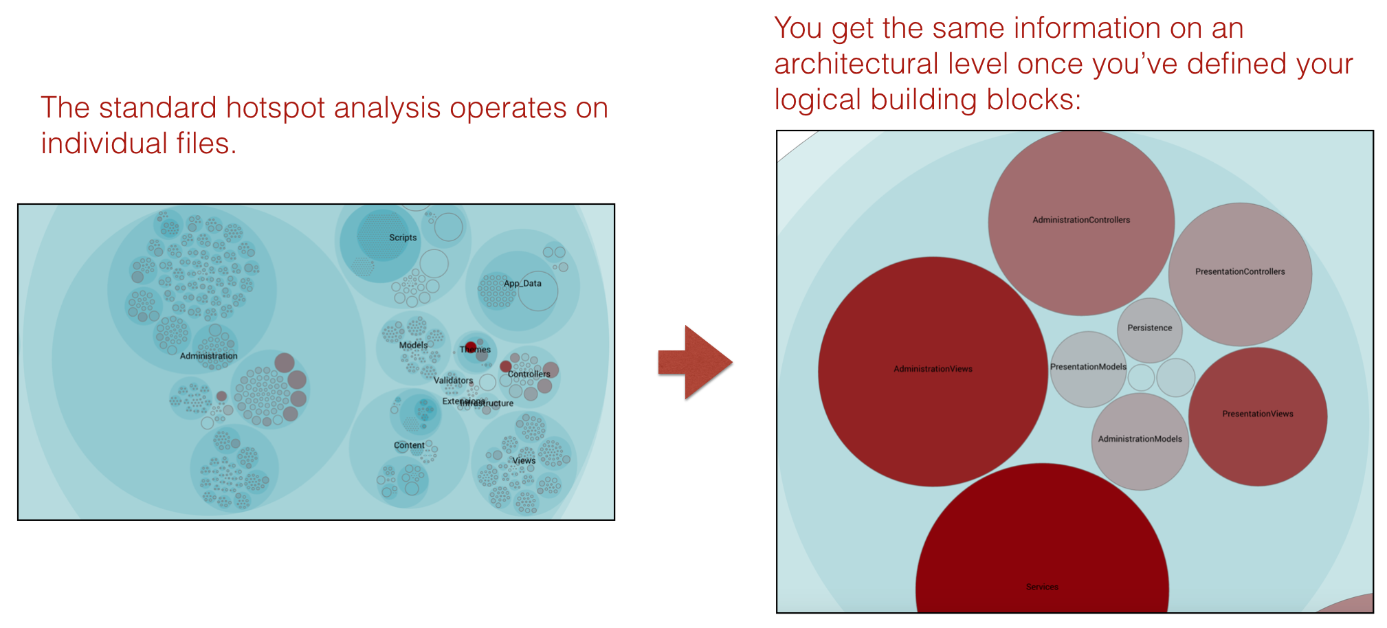
Fig. 131 Using the hotspot analysis for architectural components.
The architectural analyses also lets you inspect the complexity trends of architectural hotspots. Note that you need to enable the architectural trends in your project configuration as noted above.
Measure Architectural Change Coupling and Impact
The architectural analyses let you measure and visualize change coupling between architectural components.
You use this information to:
identify expensive modification patterns,
ensure that your dependencies match the architectural principles, and
to measure how well your software architecture supports the way your system evolves.
The analysis also includes a trend measurement where CodeScene detects dependencies that grow stronger over time. This information is particularly useful for complex, distributed systems like microservices.
Fig. 132 shows an example in Spinnaker, a microservices codebase where each service is located in a separate Git repository.
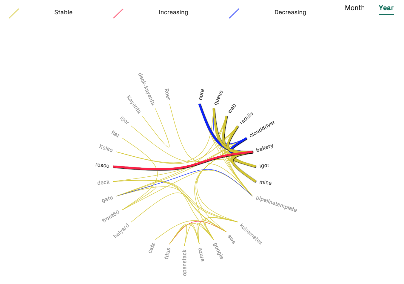
Fig. 132 Change coupling between different microservices.
From here, CodeScene lets you dig deeper and explore the change coupling between individual files, potentially located in separate Git repositories as shown in Fig. 133.
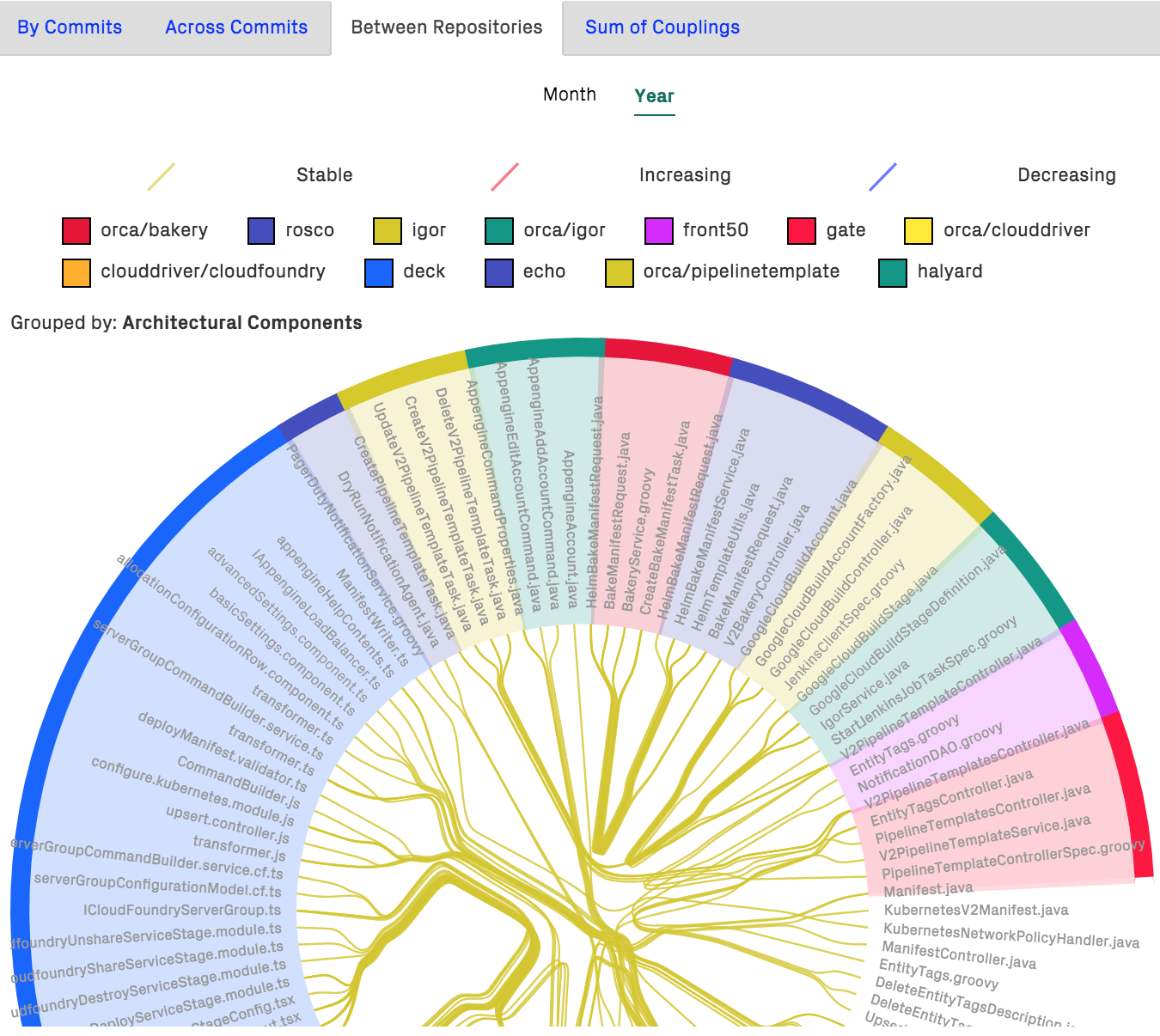
Fig. 133 Change coupling between files implemented in different programming languages and located in separate Git repositories.
Of course, the architectural change coupling works well in a monolithic codebase as well.
Evaluate Conway’s Law
CodeScene measures the knowledge distribution on an architectural level too. This gives you a powerful tool to evaluate how well your architecture aligns with your organization, aka Conway’s Law as illustrated in Fig. 134.
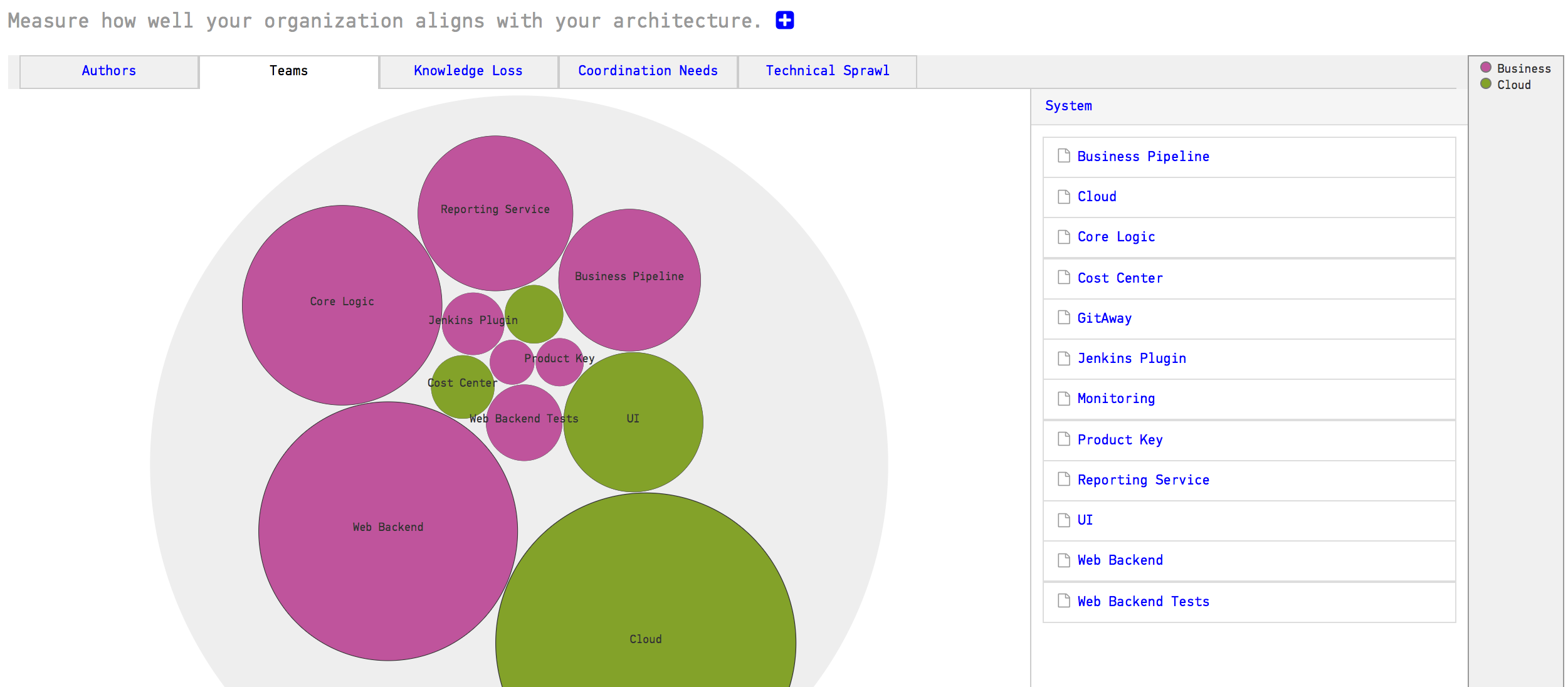
Fig. 134 Measure Conway’s Law in your codebase.
The same analysis also lets you measure the coordination needs on an architectural level. This is useful to detect sub-systems that become coordination bottlenecks or lack a clear ownership, as illustrated in Fig. 135.
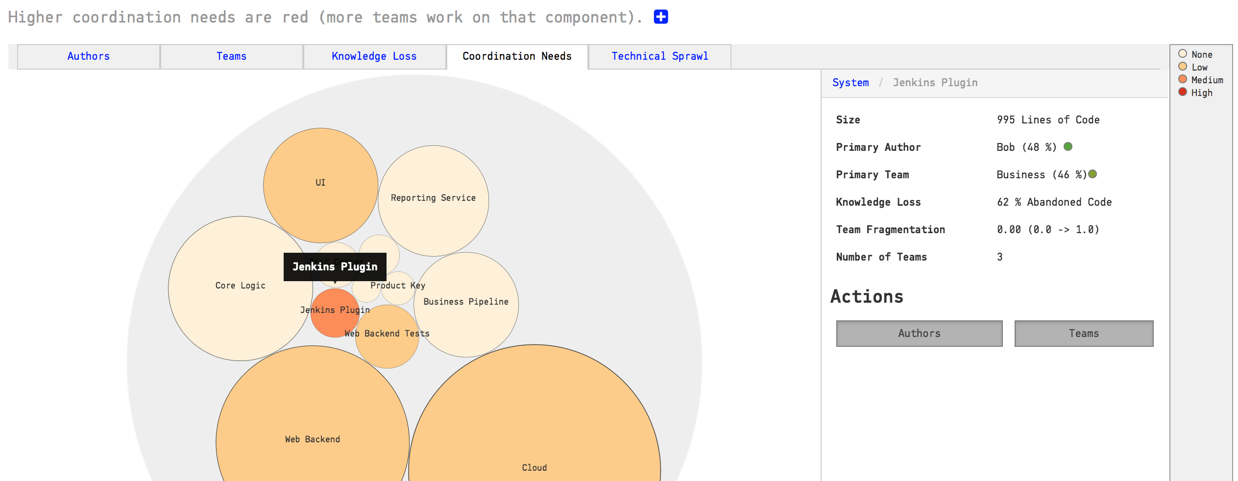
Fig. 135 Find team coordination bottlenecks.
You use this information to find parts of the code that may have to be split into smaller parts to facilitate parallel development, or, to introduce a new team into your organization that takes on a shared responsibility.
The high-level analyses are particularly useful if you work on a (micro) service oriented architecture. In that case you also want to investigate Technical Sprawl, which we discuss next.
Measure Technical Sprawl
One of the big selling points behind Microservice architectures is the freedom of choice when it comes to implementation technologies. Using a Microservice architecture, each team is free to chose the programming language they think makes the best fit for the problem at hand.
In practice, however, this freedom may lead to a sprawl in programming languages that makes it hard to rotate teams. It also puts you – as an organization – at risk when the only people who master a particular technology leaves. Thus, CodeScene provides analyses to measure your technical sprawl, as illustrated in Fig. 136.
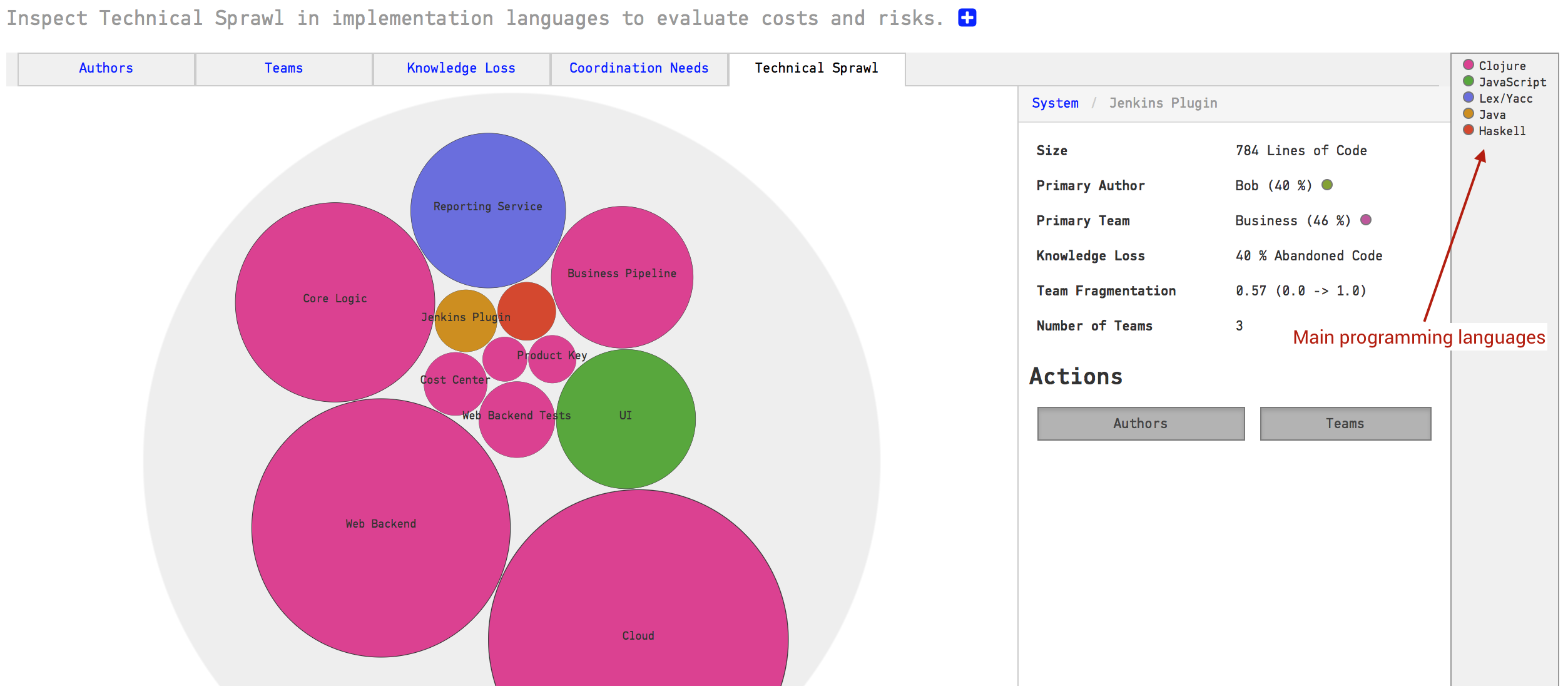
Fig. 136 Technical Sprawl shows the main programming language used for each component or service.
The technical sprawl analysis is particularly useful for off-boarding. Let’s say that we want to move a developer to another project or, worse, someone decides to leave the organization. In that case we run a pro-active simulation of knowledge loss (see Knowledge Distribution) and ensure that we still have the technical competencies we need within the organization, as illustrated in Fig. 137.
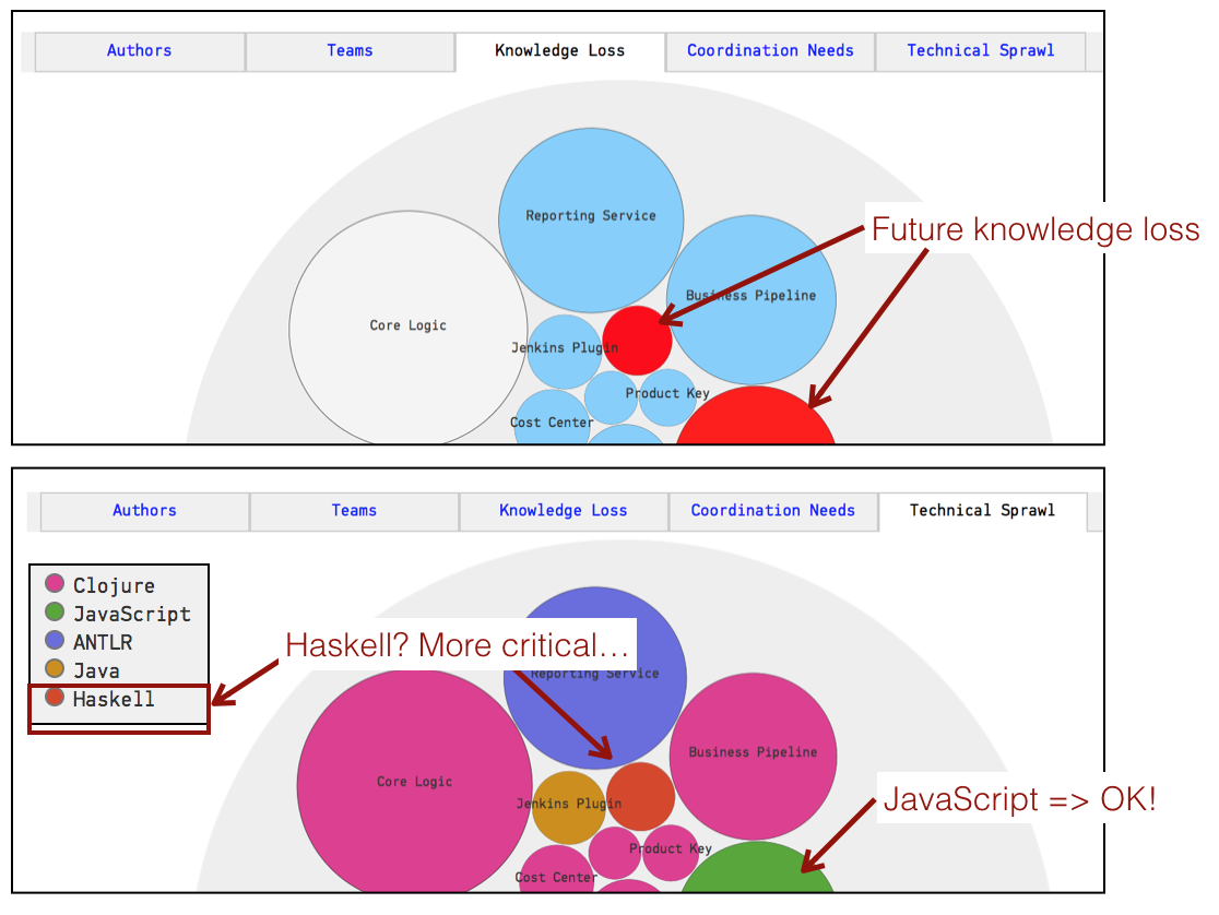
Fig. 137 Combine Technical Sprawl with Knowledge Loss for off-boarding.